Transitioning a custom tool concept from a CAD file to a market-ready product involves significant capital risk, complex supply chain orchestration, and strict engineering tolerances. Procurement managers and brand owners frequently face misaligned manufacturing specifications, unexpected tooling costs, and delayed time-to-market when sourcing custom hand tools. A poorly managed transition from prototype to mass production compromises product integrity and brand reputation. Mitigating these risks requires a rigorous, phased Original Equipment Manufacturer (OEM) workflow. This guide breaks down the technical evaluation, validation milestones, and production stages required to successfully launch an OEM tool kit project.
- Design for Manufacturing (DFM) dictates profitability: Early collaboration on material selection and tolerances prevents costly mold modifications during the tooling phase.
- Factory vetting prevents structural failures: Vetting an OEM partner's in-house testing capabilities and supply chain transparency is as critical as the CAD design itself.
- First Article Inspection (FAI) is the critical go/no-go milestone: Rigorous testing of pre-production samples against ANSI/DIN standards is non-negotiable before approving mass production.
- Packaging and configuration impact scalability: The choice between a modular aluminum case or a heavy-duty rolling chassis directly affects shipping logistics, assembly time, and final unit economics.
- IP protection requires contractual and operational boundaries: Securing intellectual property involves strict NDAs, compartmentalized manufacturing, and clear ownership of custom molds.
Defining the Scope and Success Criteria for a Professional Tool Set
Establishing the baseline technical requirements and end-user performance expectations before engaging an OEM facility prevents misaligned capabilities. You must define exact metallurgical properties, load tolerances, and spatial constraints before cutting any steel for molds.
Establishing End-User Requirements and Load Tolerances
Identify the target demographic to dictate torque requirements, insulation standards, and ergonomic needs. Aviation mechanics demand strict foreign object damage (FOD) compliance and precise dimensional tolerances. Industrial electricians require VDE-certified insulation rated for 1000V. Automotive technicians need high-torque impact resistance and chemical-resistant handles that withstand brake fluid and degreasers.
Define the required metallurgical properties based on expected wear and shear strength. Chrome Vanadium (Cr-V) serves as the industry standard for wrenches and sockets due to its balance of hardness and corrosion resistance. S2 Steel provides superior shock resistance, making it mandatory for high-impact driver bits and hex keys. Specify the exact Rockwell Hardness (HRC) ranges required for each tool category. Sockets typically require HRC 42-48, while cutting pliers demand HRC 58-62 at the cutting edges.
Selecting the Right Configuration and Housing
Evaluate the structural requirements for a high-capacity rolling tool set. Specify caster load ratings, demanding polyurethane wheels with dual ball bearings capable of supporting at least 300 lbs per caster. Telescopic handle durability requires heavy-gauge tubular steel or extruded aluminum to prevent bending under full load. Drawer slides must feature ball-bearing mechanisms with a minimum 100 lb capacity per drawer, incorporating soft-close or detent retention to prevent accidental opening during transit.
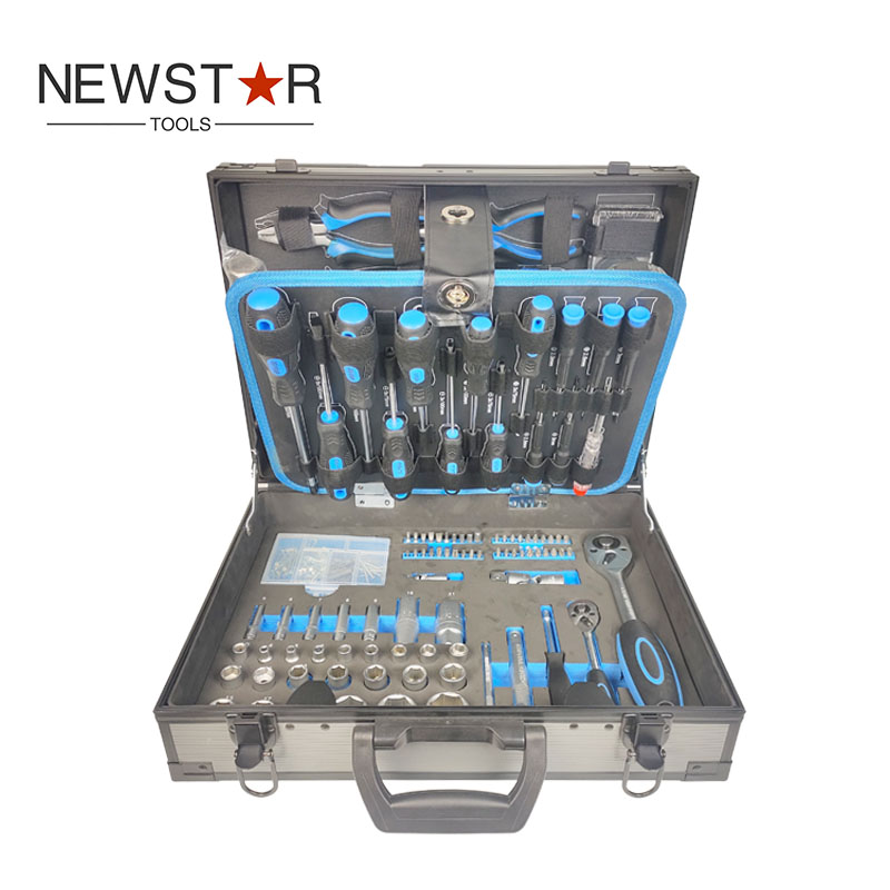
Assess the weight-to-durability ratio for an aluminum case tool set. Focus on reinforced steel corners, heavy-duty toggle latches, and continuous piano hinges. The interior requires custom EVA foam inserts. Specify high-density, closed-cell EVA foam routed via CNC to exact tool profiles. This ensures tools remain secure during drop tests and heavy vibration.
Determine the specific tool matrix required for a comprehensive multifunction hand tool set. Avoid redundant inclusions that add weight without utility. Optimize spatial efficiency by nesting smaller tools within the negative space of larger handles. Map out the exact bill of materials for the tool matrix, ensuring a logical progression of drive sizes (1/4", 3/8", 1/2") and metric/SAE equivalents.
Vetting the OEM Partner for Technical Competency and IP Security
Establish strict criteria for selecting an OEM factory. Verify their on-site testing laboratories. A competent facility must possess optical emission spectrometers to verify raw steel composition. They need salt spray chambers to test chrome plating durability and life-cycle testers for ratcheting mechanisms. Conduct physical factory audits focusing on quality management systems. Verify ISO 9001 compliance and trace their raw material supply chain back to the steel mill.
Implement legal and operational safeguards to protect proprietary tool geometries. Use multipartite NDAs. Compartmentalize tool component production across different sub-suppliers. Have one facility forge the steel blanks, another handle the plastic injection molding for grips, and a third manage final assembly. This prevents any single factory from possessing the complete technical data package for your product.
![Factory floor production line for hand tools]()
Phase 1: Design for Manufacturing (DFM) and Prototyping
Adapting conceptual designs to match the physical realities of factory floor machinery requires a dedicated DFM phase. Engineers must translate aesthetic concepts into manufacturable geometry.
Translating Concepts into Manufacturable Specs
Convert initial 3D models into production-ready 2D technical drawings. Detail dimensional tolerances, surface finishes, and draft angles. Forging dies require specific draft angles (typically 3 to 5 degrees) to allow the hot steel blank to release from the die. Injection-molded handles need uniform wall thickness to prevent sink marks during cooling.
Leverage existing manufacturer supply data to identify off-the-shelf components. Integrating standardized fasteners, standard driver bit profiles, and common spring mechanisms minimizes custom tooling requirements. This accelerates development and reduces upfront capital expenditure. Create a highly detailed Bill of Materials (BOM). Specify raw steel grades (e.g., 50BV30 for sockets), plastic monomer compounds (e.g., TPR and PP for dual-component handles), and surface treatments (e.g., mirror chrome plating, matte satin finish, or black oxide).
Prototype Validation and Functional Testing
Utilize CNC machining or 3D metal printing to create physical prototypes. Evaluate ergonomic and spatial constraints in the target layout. Machined prototypes allow engineers to test the grip diameter, balance, and tactile feel of the tool before cutting expensive production molds.
Conduct preliminary stress tests to identify potential failure points. Apply static loads to wrench jaws to measure deflection. Test ratchet gear teeth for shear strength under maximum torque. Identifying a weak cross-section in a prototype costs a few hundred dollars to fix in CAD. Discovering the same flaw after machining a $20,000 forging die destroys project budgets.
Phase 2: Tooling, Sampling, and Non-Production Release (NPR)
Assessing the capital investment in molds and validating the initial output forms the core of the NPR phase. This stage transitions the project from digital files to physical steel.
Mold Creation and Tooling Investment Trade-Offs
Analyze the cost-benefit of single-cavity versus multi-cavity molds. Single-cavity molds cost less upfront but yield lower production rates, suitable for low-volume specialty tools. Multi-cavity molds require higher initial capital but drastically reduce the per-unit cost for high-volume items like standard sockets or screwdriver handles. Establish clear contractual ownership of all custom tooling, dies, and molds. The contract must explicitly state that the buyer owns the molds upon final payment, preventing the factory from using your proprietary dies to manufacture tools for competitors.
Evaluating the First Article Inspection (FAI) and NPR Milestones
Execute a comprehensive review of the first off-tool samples (T1 samples). Measure physical dimensions against CAD data using Coordinate Measuring Machines (CMM). Ensure absolute compliance with the technical spec sheet. Document necessary tooling modifications to correct flash, sink marks, or dimensional inaccuracies.
| Sample Phase | Primary Objective | Key Inspection Focus | Required Action |
| T1 (First Off-Tool) | Verify basic mold functionality and fill | Gross dimensional accuracy, short shots, major flash | Adjust injection pressure, modify gate sizes |
| T2 (Refinement) | Correct T1 issues and evaluate finish | Surface texture, sink marks, parting line mismatch | Adjust cooling times, polish mold surfaces |
| T3 (Final NPR) | Approve for mass production | Strict tolerance compliance, material hardness, assembly fit | Sign off on golden sample, authorize production |
The NPR phase requires patience. Rushing the approval of T1 or T2 samples inevitably leads to high defect rates during mass production. Demand physical samples shipped to your engineering team for independent verification. Do not rely solely on factory-provided inspection reports.
Phase 3: Quality Assurance and Compliance in Tool Manufacturing
Ensuring the manufactured product meets international regulatory and industry-specific standards guarantees safety and performance in the field. Quality assurance must be integrated into the production line, not just treated as a final sorting process.
Industry-Standard Evaluation Lenses
Verify compliance with relevant standards such as DIN (Deutsches Institut für Normung), ANSI (American National Standards Institute), or ISO specifications. These standards dictate the minimum torque failure points, dimensional tolerances for fastener engagement, and material hardness. For example, an ANSI-compliant 1/2-inch drive ratchet must withstand a specific minimum torque load without gear slippage or anvil deformation.
Implement specialized testing protocols for insulated tools. VDE certification for electrical safety requires tools to undergo a 10,000-volt water bath test to guarantee user safety under 1,000-volt operating conditions. Tools must also pass cold impact tests and flame retardancy evaluations to maintain their VDE rating.
Material Certifications and Hardness Testing
Require raw material certificates (mill test reports) from the OEM. These documents verify the exact chemical composition of the steel batch, ensuring the correct percentages of carbon, chromium, vanadium, and molybdenum. Conduct Rockwell Hardness (HRC) testing on production samples. Test multiple points on the tool to ensure uniform heat treatment. A wrench with a hard jaw but a soft handle will bend under load. Metallurgical analysis, including micro-structure examination, confirms proper tempering and the absence of internal micro-fractures.
- Extract random samples from the heat treatment batch.
- Grind and polish the test surface to ensure accurate HRC readings.
- Perform three indentations per tool and average the results.
- Cross-reference the average HRC against the engineering specification.
- Quarantine and re-temper any batches falling outside the acceptable tolerance window.
Phase 4: Scaling to Mass Production and Assembly
Managing the logistics of high-volume manufacturing, final product consolidation, and engineering communication dictates the final success of the launch. Assembly lines must operate with precision to maintain unit economics.
Supply Chain Synchronization for Components
Coordinate lead times between multiple sub-suppliers. Steel forging facilities, plastic injection molders, and case manufacturers operate on different schedules. A delay in EVA foam production halts the entire assembly line, even if all the steel tools are finished. Implement batch tracking and quality control checkpoints at each sub-assembly stage. Assign unique lot numbers to each production run to facilitate traceability in the event of a field failure.
Final Assembly, Packaging, and Labeling
Standardize the assembly line process. Workers inserting tools into EVA foam trays or blow-molded cases must follow strict standard operating procedures (SOPs) to ensure no empty slots remain. Apply custom branding via laser etching on steel components, pad printing on plastic handles, or dual-color injection molding for permanent logo integration. Finalize retail or industrial packaging designed to withstand international freight stress. Conduct ISTA drop tests on the fully loaded master cartons to verify that the packaging protects the heavy tools during transit.
Closing the Loop: Integrating Production Floor Data Back to Design Engineering
Establish formal communication protocols to feed real-world assembly data back to the engineering team. Track tolerance stack-up issues where individual parts meet spec, but the final assembly binds or fits poorly. Monitor yield rate metrics to identify specific manufacturing steps causing high scrap rates. Utilize this production floor feedback to update the master CAD models and DFM guidelines. Continuous product improvement streamlines manufacturing for subsequent production runs and drives down the overall defect rate.
Implementation Risks and Mitigation Strategies
Identifying common points of failure in OEM partnerships allows you to establish proactive defenses. Manufacturing custom tools involves inherent risks that must be managed through strict contractual and operational controls.
Managing Lead Times and Minimum Order Quantities (MOQs)
Capital tied up in excessive inventory due to high MOQs presents a major financial risk. Stockouts caused by extended production lead times damage brand reputation and disrupt retail distribution. Negotiate tiered pricing structures and phased delivery schedules. Establish buffer stock agreements for critical raw materials. By paying the factory to hold raw steel or blank forgings in inventory, you can drastically reduce the lead time for subsequent production runs without committing to fully finished goods.
Preventing Scope Creep and Cost Overruns
Incremental design changes during the tooling phase lead to exponential cost increases and severe schedule delays. Moving a logo placement or changing a handle contour after molds are cut requires expensive EDM machining or welding. Enforce a strict design freeze prior to tooling kickoff. Require formal engineering change orders (ECOs) for any subsequent modifications. The ECO must include a detailed cost and time impact analysis, forcing stakeholders to justify the change against the project budget and launch date.
Conclusion
Successfully transitioning an OEM project from design to production requires treating the manufacturer as an engineering partner rather than a transactional vendor. Success hinges on rigorous DFM, strict FAI protocols, and continuous feedback loops between the production floor and the design room. When evaluating OEM partners for a Professional Tool Set, prioritize factories that demonstrate in-house tooling capabilities, transparent material sourcing, documented compliance with ANSI/DIN standards, and a proven track record of protecting client IP.
- Compile a comprehensive technical data package (TDP) detailing all material specs, tolerances, and 2D/3D CAD files.
- Draft and execute a mutual Non-Disclosure Agreement (NDA) before sharing any proprietary designs with potential factories.
- Issue a Request for Quotation (RFQ) to a shortlisted group of vetted manufacturers to compare tooling costs and unit pricing.
- Schedule a preliminary DFM review with your chosen factory to lock in material specs and identify cost-saving modifications.
- Establish a clear inspection protocol and sign off on the golden sample before authorizing the first mass production run.
FAQ
Q: How long does it take to move a custom tool set from design to mass production?
A: The timeline typically ranges from 4 to 8 months. DFM and prototyping take 4-6 weeks. Tooling and sampling require 6-10 weeks. Mass production adds another 6-8 weeks, depending on complexity, material availability, and factory capacity.
Q: What is the difference between OEM and ODM for hand tools?
A: OEM (Original Equipment Manufacturer) means the factory produces a product based entirely on your custom design and engineering specifications. ODM (Original Design Manufacturer) means the factory provides an existing, pre-designed product that you can brand or slightly modify.
Q: How are tooling costs managed during the NPR phase?
A: Tooling costs are usually paid upfront or amortized over a set production volume. Clear contracts must state that you own the molds once paid for, preventing the factory from using your proprietary dies to manufacture tools for other clients.
Q: What materials are best for an aluminum case tool set?
A: High-grade aluminum alloys like 6061 are preferred for the exterior frame due to their excellent strength-to-weight ratio. The interior should utilize CNC-routed, high-density EVA foam to secure the tools properly and absorb impact during transport.
Q: Why is First Article Inspection (FAI) so critical?
A: FAI verifies that the production process can consistently yield parts meeting your exact specifications. It serves as the final checkpoint to catch dimensional, cosmetic, or metallurgical errors before mass production begins, preventing costly large-scale defects.